The hardware end is based on this fine set of instructions: https://www.instructables.com/Raspberry-Pi-Controlled-Irrigation-System/
In my approach I’ve added a USB camera. You can use any USB camera. The temperature and humidity sensor is an AM2302 and can be had from here: https://www.adafruit.com/product/393
For some of you out there, those instructions are all you need. If you’re like me and less experienced with reading circuit diagrams and need more practice with soldering, read on.
Steve’s List o’ Hints:
- When you go to buy the parts, buy at least two of everything or more. Why? Well, then you can make a test circuit before you get to soldering and then you’ve also got extras if your break or lose anything. You can’t go far wrong having extra LED’s and resistors.
- If you are new to electronics and looking to learn more, check out https://hackerboxes.com. Everything I assembled here was done with their starter workshop kit.
- Build some test circuits on a breadboard. Something as simple as showing the code lighting up a single LED shows you’re making progress.
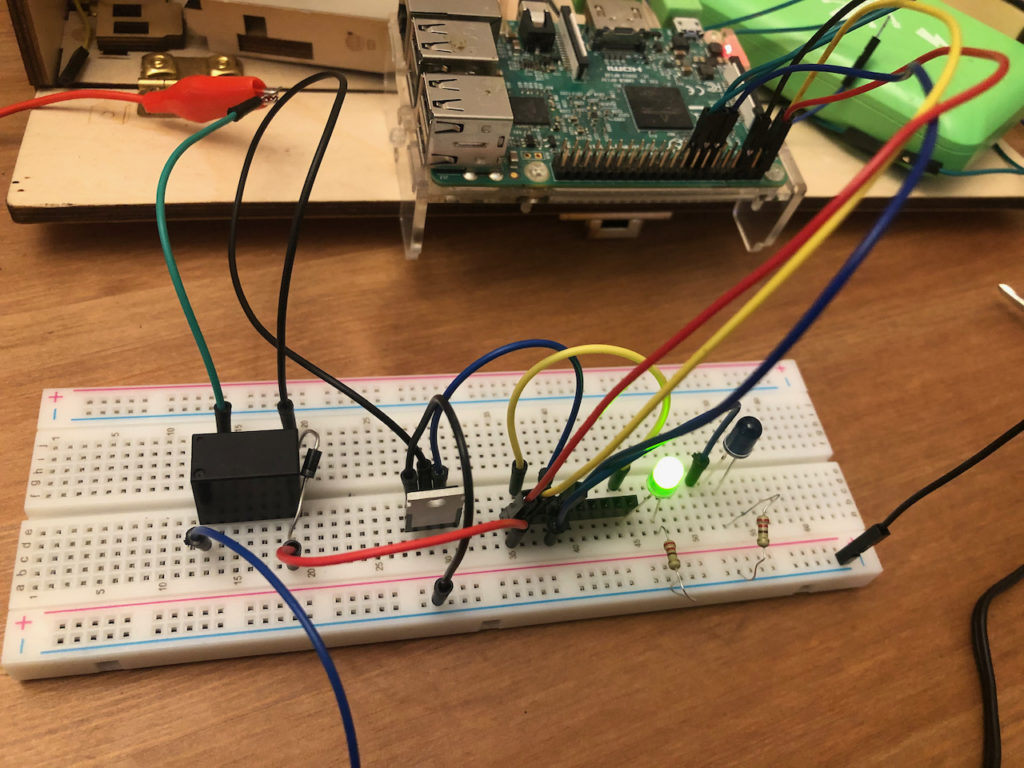
- You’ll find that having the valve and it’s power supply on your bench or work desk is cumbersome. Solution: substitute a 9-volt battery for the power supply and a simple LED circuit for the valve. All the code will work, using the 9-volt to light the LED.
- In addition to Ben’s basic relay switch, I’ve added a temp/humidity sensor and a USB camera. The sensor plugs into the GPIO ports, the USB camera plugs into the rPi USB ports.
- This is designed to be modular. I added the sensor and USB camera on top of the original design. You could take those out, and/or add other things in.
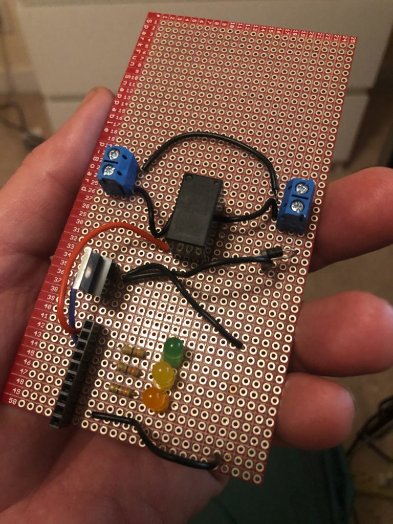
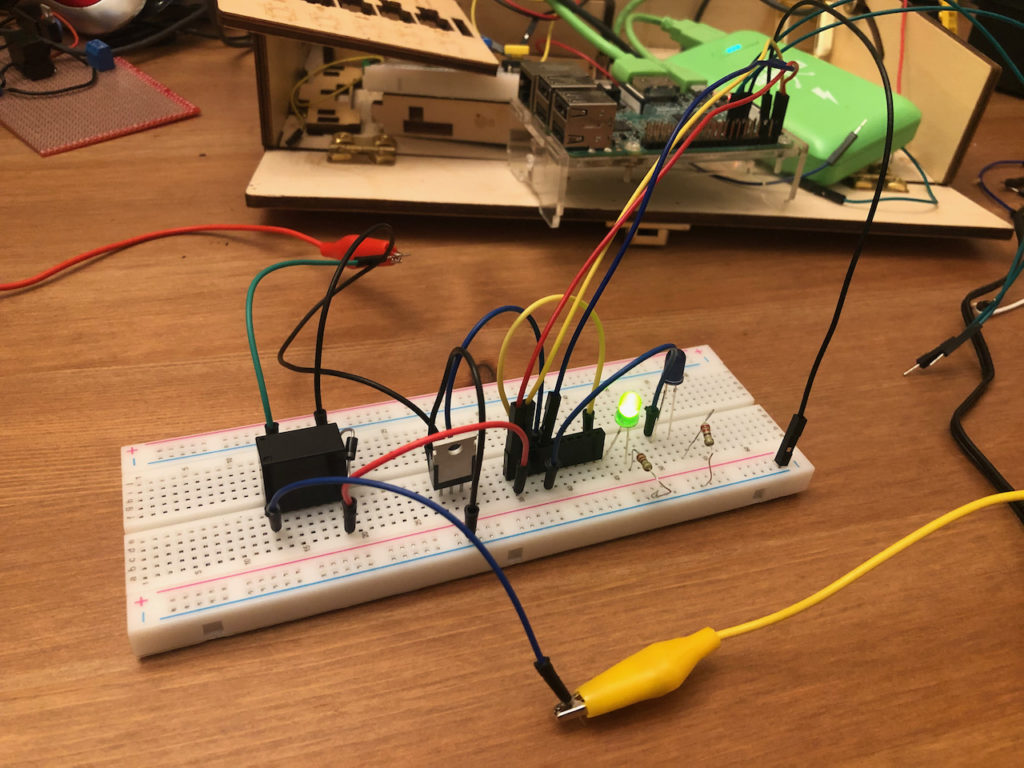
Hopefully these photos will be helpful in figuring out how it all goes together. It’s hard to see in the photos, but the flyback diode mentioned in Ben’s instructions can be seen in-line with the ground to the right if you look close.
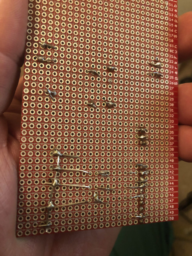
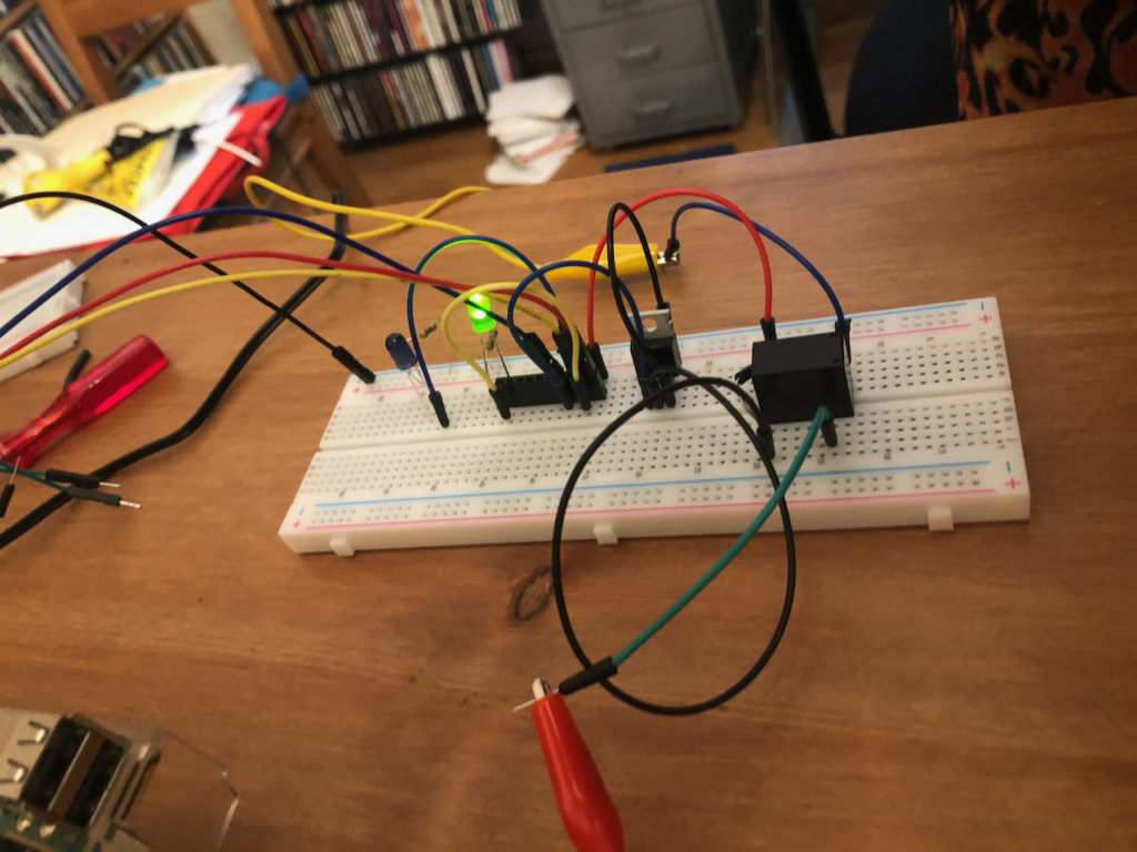
Here you see my functional, but not pretty soldering job. I show this for those who want to see what I soldered to what.
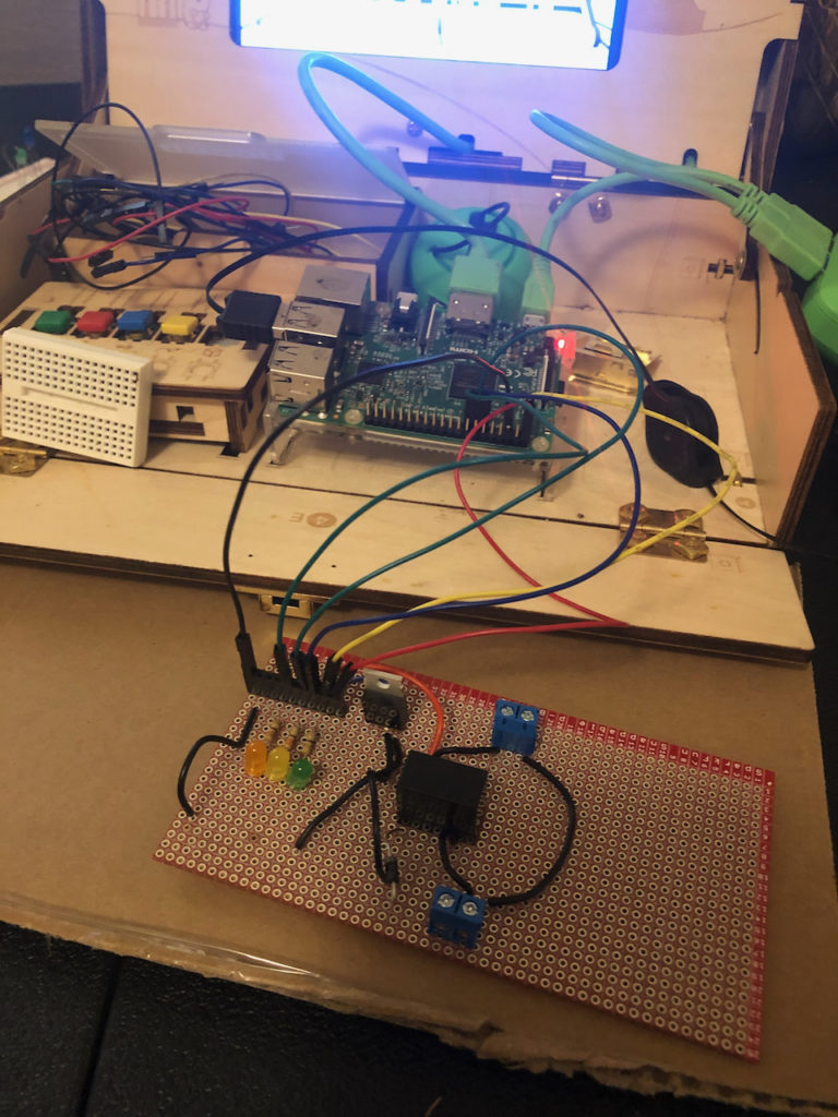
Here we have my circuit hooked up to my development rPi.
Here is three photos of my test circuit. Hopefully this will help you figure out what goes to what.
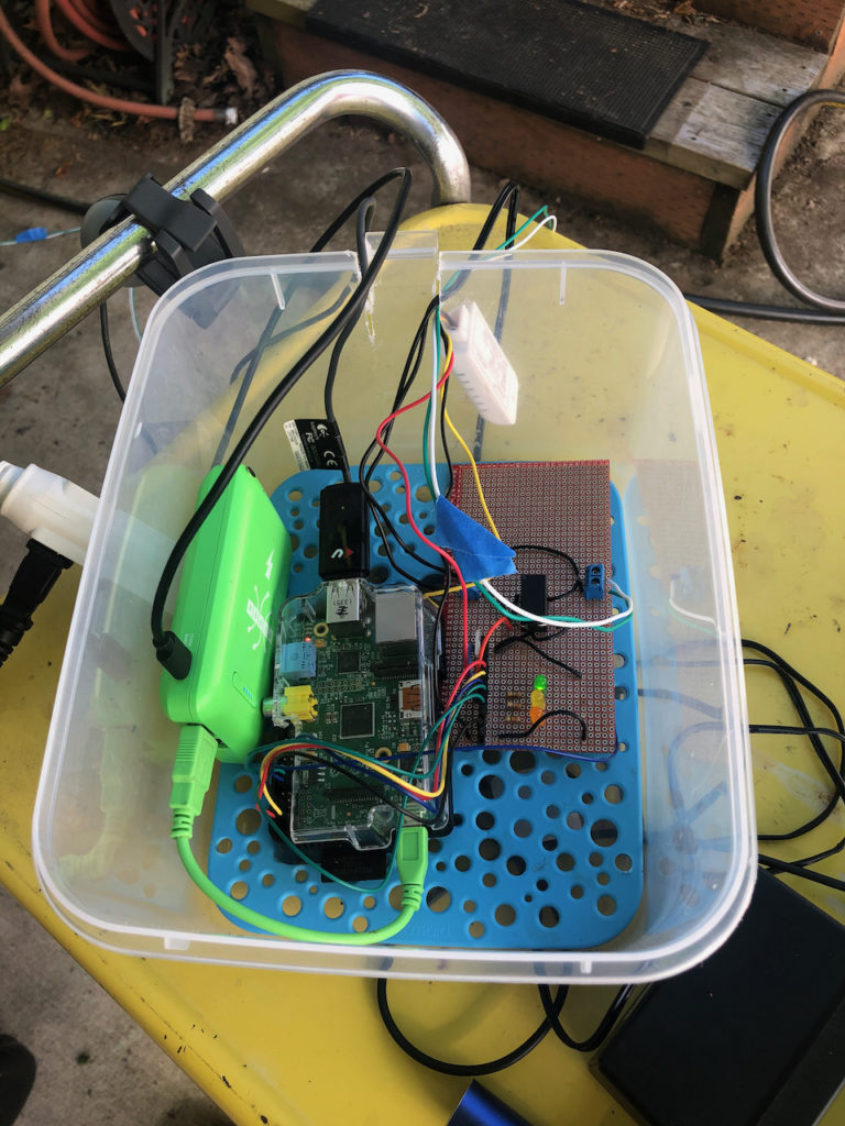
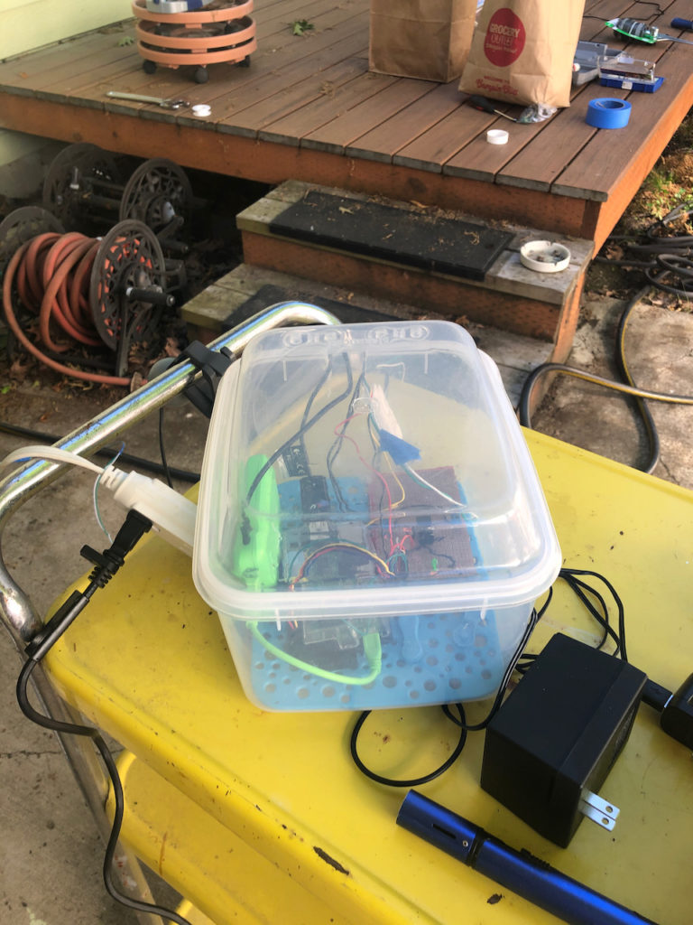
In my case, this all has to live outside. It’s not going to be in direct weather, but it needs to stay dry. Simple solution: local thrift store, Tupperware style container. In there you’ll see my rPi, the controller circuit and a USB battery that will keep the rPi up and going even if there’s a power failure. You can see the temp / humidity sensor hanging outside the box.
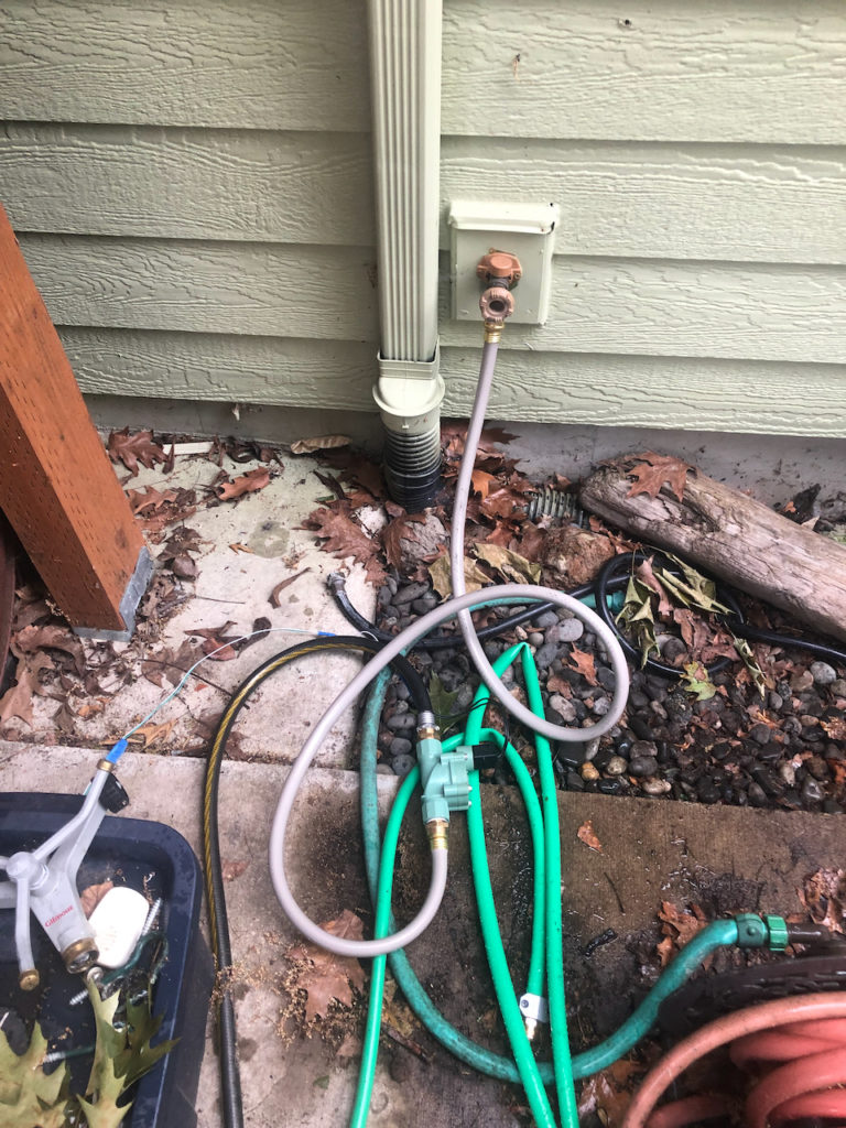
Here you can see the valve in-line with the hose. When you set this up, keep in mind that the valve connections are not the same size as regular garden hoses. So, check Ben’s instructions on that. Also keep in mind that you need the house–to–valve connection to not leak even a drop because it will be turned on 24×7.